Graphics Programs Reference
In-Depth Information
3.
Click OK. You are prompted with the option to automatically generate area boundaries
for exterior walls. Because you selected more than one level, you will receive a prompt
for each level for which a plan is being generated. Go ahead and click OK to generate the
plans automatically.
This creates new area plans under a new node in the Project Browser: Area Plans (Usable
Area).
4.
In the Project Browser, select both Level 1 and Level 2 under Area Plans (Usable Area).
Right-click and select Apply View Template from the context menu.
5.
In the Apply View Template dialog box, choose Area Plan from the list of view templates,
click OK to apply the template, and close the dialog box.
This method applies the template properties to the views, but it does not associate the
template with the views. To permanently assign the view template to the views, edit
the View Template parameter in the Properties palette.
View references, furniture, and floor patterns are turned off based on the settings defined
in the view template (Figure 17.6). For more detailed information on using view tem-
plates, refer to Chapter 4, “Configuring Templates and Standards.”
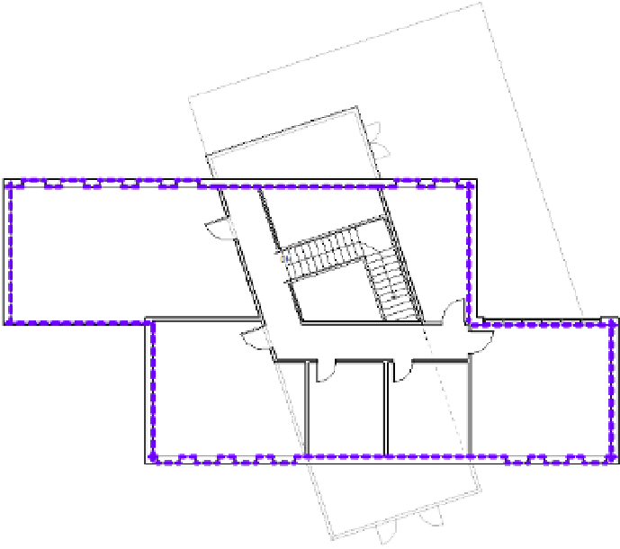
F igu r e 17.6
area boundaries have
been automatically
assigned to the
exterior walls.
When looking at the area plan on your screen, you'll notice a thick purple line running
around the inside face of the exterior wall. This is the area boundary line.
Note that we
have changed the default properties of the Area Boundary line type in the figures within this