Graphics Programs Reference
In-Depth Information
Although this detail still needs annotations before you can think about placing it onto a
sheet, you can begin to see how you have used the 3D geometry of the model and were able
to quickly add some embellishment to it to create a working project detail. For now, save this
detail. You'll return to it later in the chapter.
Using Line-based Detail Components
While there isn't a command dedicated to line-based detail components, this category of 2D
elements can be quite powerful. As their name suggests, line-based detail components
are 2D elements that behave like lines. Some examples of building elements you can illustrate
with these components include waterproofing, gypsum board, plywood, and even repeating
elements such as brick. Why would you use a line-based detail component for brick instead of
a repeating detail component as we previously discussed? Because you can tag and schedule a
line-based detail component.
You can use any modifying commands on line-based detail components such as Trim,
Extend, and Align. Unfortunately, you can only draw these components in straight lines;
therefore, you will need to decide whether it is more important to have tagging and scheduling
capability or the ability to draw curved shapes.
In the default content library you will find components in the Detail Items folder such
as Gypsum Wallboard, Rigid Insulation, and Drainage Board. Start the Detail Component
command, click Load From Library, and load a few of these families. In a detail view, practice
drawing these elements to embellish the modeled design further.
Drafting Insulation
The best way to think of the Insulation tool is as a premade repeating detail. You'll find this tool
on the Detail panel of the Annotate tab.
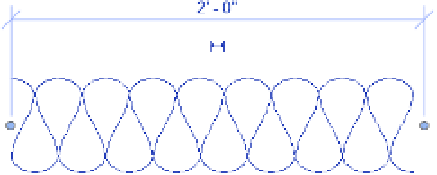
Selecting this tool allows you to draw a line of batt insulation, much like a repeating detail.
Figure 16.23 shows a typical line of insulation.
Figure 16.23
The insulation detail component
drafted in a view
When selecting the Insulation tool, you can modify the width of the inserted insulation
from the Options bar or the Properties palette. In the Properties palette, you can also control
the Insulation Bulge To Width ratio, which adjusts the amount of curve in the insulation. The
default value is 2.0. By default, insulation is inserted using the centerline of the line of batt, but
you can control the offset in the Options bar once the tool is activated. You can also modify the
width either before or after inserting insulation into your view.
Let's continue to embellish the wall section view in the c16-Sample-Project file. Follow
these steps to begin adding insulation detail components: