Graphics Programs Reference
In-Depth Information
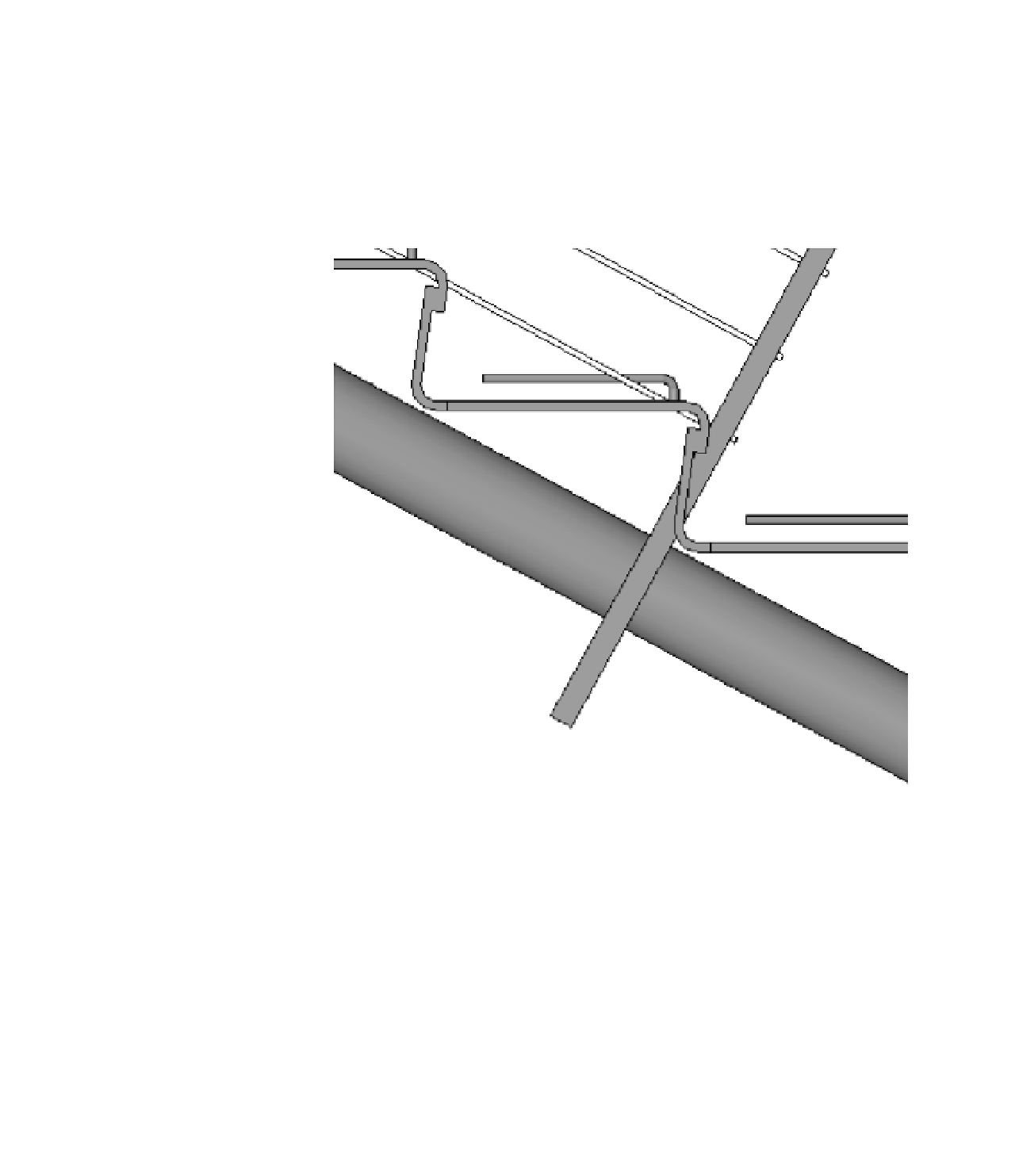
Figure 15.25 shows an example from a real stair that was designed to have each tread
fabricated from a single plate of steel and then rolled to form the face of the riser above it.
Here, each of these treads can be welded behind the lip of the tread above it. It's a fairly elegant
idea that can be accomplished by using a custom-nosing profile to create the appearance of
a continuous tread. Look closely and you can see where the actual tread ends and where the
nosing profile begins. Final linework can be adjusted or hidden (if necessary) when you're
creating the details.
Figure 15.25
Continuous tread
and nosing profile
If you're using a custom profile to represent both the nosing and the riser, be sure to set
Riser Type to None in the stair type properties. If you don't, the profile won't be assigned
correctly; it will overlap with the default riser. Figure 15.26 shows this stair in its final form
using our custom profile, but the walls are hidden for clarity. If you'd like to investigate this
stair further, it's in the Chapter 15 folder on the topic's companion website and is called
c15-Henrys Stepp.rvt.