Graphics Programs Reference
In-Depth Information
can be found in the instance properties of each run. You will need to Tab+select a run within
a stair instance to enable or disable these parameters, but it is ultimately more flexible to use
throughout your project.
Another important group of instance properties is assigned to the stair supports. If you
Tab+select a support for any component stair, you will see parameters including Lower End Cut
and Upper End Cut in the Properties palette. These can be assigned to Vertical Cut, Horizontal
Cut, or Perpendicular—options that are not available with the Stair By Sketch tool.
Using Component Stairs in assemblies
Stairs created with the component method cannot be added to assemblies. Use the Stair By Sketch
method if you intend to document a stair with the assembly functionality. See Chapter 19, “working
in the Construction Phase,” for more information about assemblies.
Using the Components for Customizing Stairs
A key concept in making the best use of Revit is to not get hung up on how elements and tools
are named or labeled. For example, you can use the Railing tool to create a shading device—
which is obviously not a railing. This same concept applies to stairs—don't overlook the nosing
profile family as a device for creating interesting shapes that complete the tread because the
shape of the nosing is not limited to traditional-nosing profiles. Any shape that needs to extend
beyond the face of the tread is fair game to model with the nosing profile family. Just remember
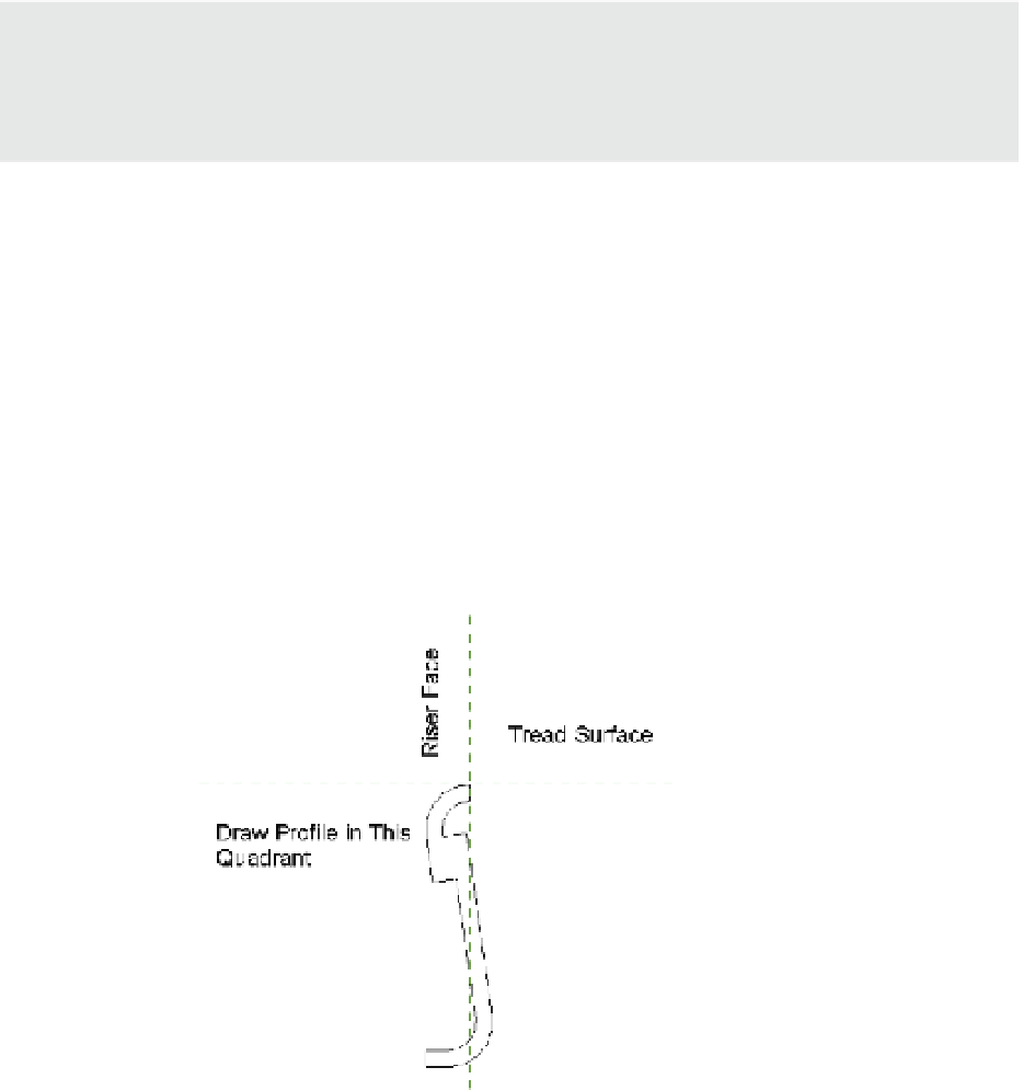
that you're limited to a single profile per tread and stair run (Figure 15.24). You'll also want to
pay particular attention to the insertion point of the nosing profile, because the intersection of
the reference planes coincides with the top of the tread and the face of the riser.
Figure 15.24
Custom-nosing
profile