Graphics Programs Reference
In-Depth Information
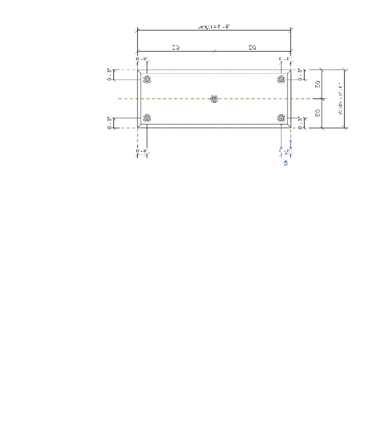
Figure 14.45
leg families
are placed and
dimensioned in a
plan view.
You can do this a few different ways, but when you're dealing with multiple instances
of an object, we recommend you feed a value into a nested type parameter rather than
aligning and locking each instance to reference planes within the host family.
7.
Select one of the legs, and then click the Edit Type button in the Properties palette. In the
Type Properties dialog box, click the Assign Family Parameter (AFP) button for the Leg
Height parameter. Add a new parameter named Nested Leg Height.
8.
Click the AFP button for the Leg Material parameter, and add a new parameter named
Nested Leg Material. Click OK to close the Type Properties dialog box.
You must associate the parameters in nested families with parameters in the host
family—even if it is simply to allow materials to be assigned to the nested elements.
9.
Open the Family Types dialog box. In the Formula field for the Nested Leg Height
parameter, type the following: Height - Tabletop Thickness.
Make sure that the parameters are spelled exactly because they are case sensitive. This
formula will use the overall height of the table minus the thickness of the tabletop to
drive the height of the nested legs.
10.
Switch between Type 1 and Type 2 to verify the behavior of the legs. Even though the
middle leg is still visible in the Family Editor, it will be invisible when the family is
loaded into the project environment.
Save the table family and load it into the c14 Desk Project file, referenced previously
in this chapter. Place some instances of each type and observe the differences in size and
number of legs (Figure 14.46).