Graphics Programs Reference
In-Depth Information
sequence of images, a simpler solid form is generated and then converted to a non-cutting void,
a path is generated along the edges of the void geometry, and a tube profile is applied to the
path. To explore how this family was made, download the file c14 Tube Chairs.rvt from this
book's web page.
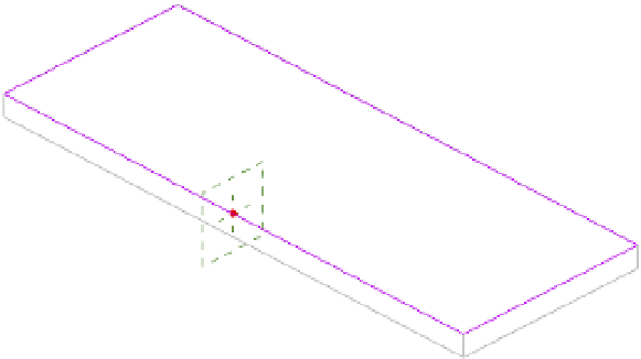
Figure 14 .33
Void geometry
used to drive a
complex sweep
path
In this part of the chapter exercise, you will create a void sweep along the outer edge of the
tabletop using the Pick Path tool. You will then assign a parameter to drive the void into or away
from the solid extrusion, depending on which type is specified.
1.
Activate the default 3D view and set the graphic style in the view control bar to Shaded.
Open the Family Types dialog box, select Type 2 in the Name drop-down list, and then
click OK.
2.
From the Create tab, choose Void Forms
➢
Void Sweep. From the contextual tab in the
ribbon, click Pick Path. In the 3D view, pick each of the four upper edges of the tabletop
solid (Figure 14.34).
Figure 14.34
Use the Pick Path
tool to select the
edges of the solid
tabletop.