Graphics Programs Reference
In-Depth Information
2.
In the Options bar, set the Depth to
-0
'-
2
” (
-50
mm).
This will allow the top of the extrusion to be aligned with the Top reference plane with its
thickness extruding downward—away from the work plane.
3.
In the Properties palette, set Subcategory to Tables. For the Material parameter, click the
small button to the right of the parameter value field.
This button will allow you to associate a family parameter to the property instead of
simply choosing one material to be assigned to the solid.
4.
Click the Add Parameter button and create a new parameter named
Tabletop Material
.
Click OK to close both open dialog boxes, and then you will see that the Material field is
now inactive and the small button now has an equal sign label.
This means that the property is now being controlled by a family parameter.
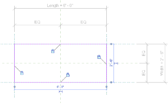
5.
In the Draw panel, choose the Rectangle tool, and then sketch a rectangle that snaps to the
intersections of the outer reference planes (Left, Front, Right, and Back). Immediately after
your second click to complete the sketch, you will see padlock icons at each of the four
sides of the sketch. Click each one to establish an alignment constraint with the respective
reference plane (Figure 14.31). If you click away and the constraint icons disappear, you
will either have to delete and redraw the sketched lines, or you can use the Align tool to
reestablish the constraint.
Figure 14 .31
set the constraints
of the extrusion
sketch to reference
planes.
Click Finish Edit Mode from the contextual tab in the ribbon, and you'll see the first solid
piece of your exercise family. Activate a 3D view and open the Family Types dialog box.
Switch between Type 1 and Type 2, and click Apply to verify that the extrusion flexes like
the reference planes did previously in the chapter.