Graphics Programs Reference
In-Depth Information
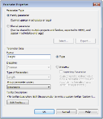
Figure 14.18
assign your first
dimension to a
new parameter.
4.
Activate the Ref. Level floor plan. You now need to ensure that the four new reference
planes are equally placed around the two planes that define the family origin. After the
equality constraints are established, you will place dimensions to control the overall
length and width of the shape. The order of this procedure—equality, then overall
dimension—should be followed to establish the correct relationship with a center-based
origin.
5.
Place an aligned dimension between the three vertical reference planes, and then click
the EQ symbol near the dimension string. Repeat this process for the horizontal reference
planes so that the result looks like Figure 14.19.
Figure 14.19
set equality constraints
on reference planes
first.