Graphics Programs Reference
In-Depth Information
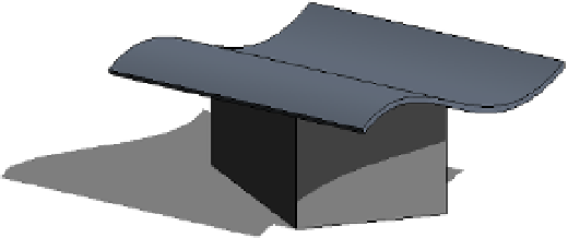
The extrusion is usually based on a work plane that is not perpendicular to the building
footprint, as shown in Figure 13.32. If the shape of the building is nonrectangular in footprint
or the shape of the roof you want to create is not to be rectangular, this tool will let you carve
geometry from the roof to match the footprint of the building or get any plan shape you need
using a plan sketch.
Figur e 13.32
extruded roof created
at an angle to the
building geometry
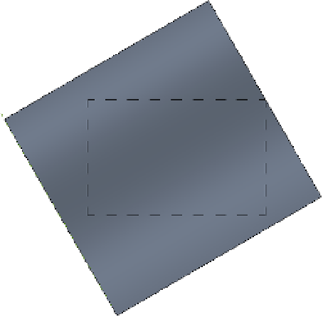
With sketch-based design, any closed loop of lines creates a positive shape; every loop inside
it is negative, the next one inside that negative one will be positive, and so on. In Figure 13.33, a
roof by extrusion was drawn at an angle to the underlying walls, but the final roof shape should
be limited to a small offset from the walls. To clip the roof to the shape of the building footprint,
the Vertical Opening tool was used to draw, in plan view of the roof, a negative shape that will
remove the portions of the roof that extend beyond the walls.
Figur e 13.33
The Vertical open-
ing tool with two
sketch loops trims
the roof to the inner
loop.
Roof In-place
The roof in-place technique accommodates roof shapes that cannot be achieved with either
of the previously mentioned methods. It is the usual way to model historic roof shapes or
challenging roof geometries such as those illustrated in Figure 13.34. The figure shows a