Graphics Programs Reference
In-Depth Information
2.
Click the Modify tab in the ribbon, activate the Split Face tool from the upper-right corner
of the Geometry panel, and pick the floor in the Level 1 floor plan.
3.
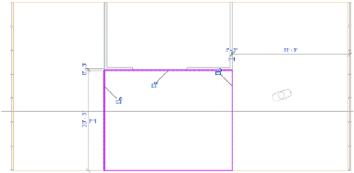
Draw a rectangle in front of the three interior walls, as shown in Figure 13.17.
F igu r e 13.17
sketch a rectangular
boundary with the
split Face tool.
You can constrain—or lock—the sketch lines to the interior walls, reference planes, and
floor edge. You may do so in this exercise, but constraints should be used sparingly in
larger projects to avoid slower model performance and updating calculation time.
Also notice that you generated a complete rectangular sketch instead of only three
bounding lines. You do not need to draw the boundary line at the edge of the floor; how-
ever, if you don't include that line and the floor shape is modified in the future, the split
face may be deleted because it is no longer a closed-loop sketch.
4.
Click the Finish Edit Mode icon in the Mode panel.
5.
Return to the Modify tab in the ribbon and activate the Paint tool in the Geometry panel,
just below the Split Face tool.
6.
In the Material Browser, type
carpet
in the filter search at the top.
This will minimize your choices, allowing you to select Carpet Tile from the filtered list
(Figure 13.18).
7.
In the Level 1 floor plan, click near the edge of the split face you created earlier to assign
the material.
The result should look like Figure 13.19.
8.
Click the Done button in the Material Browser to exit the Paint command.