Graphics Programs Reference
In-Depth Information
3.
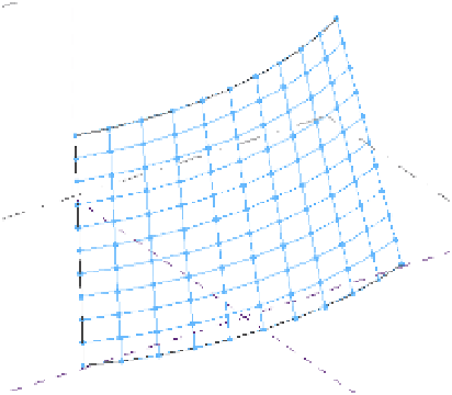
On the Surface tab, enable Nodes if is not already enabled; this will display a node at each
intersection of the UV grid, as shown in Figure 12.57.
Figure 12.57
nodes are
displayed at the
intersections of
the u grids and V
grids.
adding Definition
So far, you have created a surface, subdivided it, and applied a graphical representation to
the form. You can now begin to add actual component geometry similar to mullions and
panels. Although the underlying graphic pattern will remain, the component geometry will
take precedence. To begin this process, you will create special curtain panel families using
the Curtain Panel Pattern Based.rft or M_Curtain Panel Pattern Based.rft family
template. This type of panel family can be applied to the divided surface to populate it with
architectural components, adding realistic definition to your conceptual curtain wall surface.
Building a Pattern-Based Panel Family
In the following exercise, you will build a simple rectangular panel and apply it to your divided
surface:
1.
Click the Application menu, choose New
➢
Family, and select the Curtain Panel
Pattern Based.rft family template.
Figure 12.58 shows the pattern-based curtain wall family template, which consists of
a grid, a series of reference lines, and adaptive points. The grid is used to lay out the
pattern of the panel. The adaptive points and reference lines act as a rig, defining the
layout of the panel. You can construct solid and planar geometry within and around the
reference lines to form the panel.
When a panel is applied to a divided surface, the points in the panel adapt to the UV
grid and the panel will then flex accordingly. As a general rule, the grid pattern in your
curtain panel family should match the pattern on the divided surface to which it is
applied. For example, if you have applied a hexagonal pattern to your divided surface,
make sure the curtain panel family is also using a hexagonal pattern.