Graphics Programs Reference
In-Depth Information
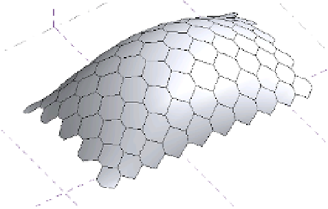
Figure 12.55
Border parameter
set to empty
Editing a Surface Representation
When editing a surface in the conceptual design environment, you have the option to choose
how surface elements will be displayed. A number of options are available to you, allowing
you to customize how you show or hide the various elements that make up a divided surface
in a view. If you select either the U or V Grid icon, this will enable or disable the UV grid in
the view. The Surface icon allows you to display the original surface, nodes, or grid lines. The
Pattern icon allows you to hide or display the pattern lines or pattern fill applied to the surface.
The Component icon allows you to hide or display the pattern component applied to the surface.
If you decide to make any changes to the display using the Surface Representation tools, these
changes will not carry through into the project environment. To globally show or hide surface
elements, you will have to alter this from the Visibility/Graphic Overrides dialog box.
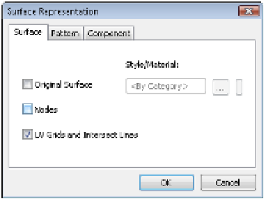
In the Surface Representation panel, you will also notice a small arrow in the bottom-right
corner. Clicking this arrow will open the Surface Representation dialog box, where you will find
additional display options for the surface, patterns, and components. You also have the ability
to display nodes and override the surface material of the form. Let's practice controlling the
surface representation of your form:
1.
Start by opening c12-Square-Panel-SurfaceRep.rfa from this topic's companion
website.
2.
With the surface selected, go to the Surface Representation panel in the ribbon, and click
the arrow in the bottom-left corner to open the Surface Representation dialog box
(Figure 12.56).
Figure 12.56
use the surface
representation
dialog box to further
customize the display
of your form.