Graphics Programs Reference
In-Depth Information
you try to do one like the other, the result is a lot of wasted time and frustration. Consider a
documentation-based design process to create a building that moves from intent to content:
1.
Host components (walls, floors, and roofs)
2.
Hosted components (doors and windows)
3.
Furniture, fixtures, and equipment
4.
Assembly details and documentation
The challenge is that this process does not provide an optimal workflow for creating great
renderings. If you're focused on the process of
visualization
, the ideal workflow is more along the
lines of the following:
1.
Geometry (host and family components)
2.
Cameras (setting up your views)
3.
Lighting (using matte materials)
4.
Materials
Yes, this is as simple as it gets: cameras, and then lights, and then materials. In a
documentation-based process, lights don't usually show up until the building is well resolved
because you're placing lights meant to be the actual fixtures to be installed in the building,
not just for rendering. So the documentation process is simply out of sequence with the
visualization process.
Additionally, you need to evaluate the lighting neutrally, without materials to distract you.
As you're placing your content, a lot of elements already have material assignments. You need to
find a way to neutralize the material settings while you figure out lighting. Now you just need
to put it all together!
Creating perspective Views
The tasks of creating and modifying your camera views are almost as important as the model
content you're creating. If you're not careful, you can easily fail to impress the viewer by
selecting the wrong view and aspect ratio of the camera and controls.
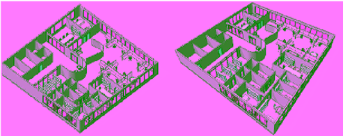
Perspective views communicate far more depth than orthographic views (Figure 11.46). Unless
the view needs to be at dimensioned scales, we prefer to use perspective views of the project.
Figure 11.46
orthographic vs.
perspective view