Graphics Programs Reference
In-Depth Information
Illustrating the Geometry Phase
Here's a simple exercise to illustrate each of the phases in a single view. Download and open
the c10-Phases-Start.rvt ile from the topic's companion website at
www.sybex.com/go/
masteringrevit2015.
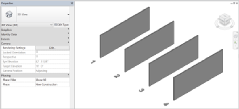
Activate the default 3D view (Figure 10.14).
Figure 10.14
Four generic walls
By default, all of these walls have been created in the New Construction phase because
the phase of the view is New Construction. Now, selecting each of the walls from left to right,
associate them with each of the following phase settings:
Wall 1: Phase Created: Existing/Phase Demolished: None
Wall 2: Phase Created: Existing/Phase Demolished: New Construction
Wall 3: Phase Created: New Construction/Phase Demolished: None
Wall 4: Phase Created: New Construction/Phase Demolished: New Construction
It's hammer time
Throughout most of this chapter we show you how to set the Phase demolished property in the
Properties palette, but there's a more fun way to change this parameter. in the Modify tab of the rib-
bon, within the geometry panel you will find the demolish hammer. activate this tool and you can
simply click model elements in the active view to set their Phase demolished property to the phase
of the view. it's even been suggested to autodesk to include a hammering sound effect to this tool!
In Figure 10.15, you'll notice that the Existing (not Demolished) and the Proposed (not
Demolished) look similar. Graphically, this might not be enough to demonstrate the different
phases, so let's change the graphic properties of the Existing wall so it's visually more distinct.