Graphics Programs Reference
In-Depth Information
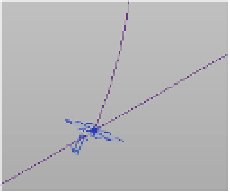
Figure 9.17
aligning the points
and reference lines
7.
Now, you need to make several versions of this—points with intersecting lines—one
set for each of your adaptive components. Open one of your elevations (it doesn't matter
which one) by selecting one of the elevation sides of the ViewCube. Draw a selection
box starting on the left and going right over the ground plane so you encompass the
levels, points, and lines you've been drawing. You'll have selected too much, but that's
okay. With everything selected, click the Filter tool in the contextual tab of the ribbon.
In the Filter dialog box, uncheck Levels, Reference Points, and Reference Planes so only
Reference Lines is selected. Click OK to close the dialog box.
8.
With these items selected, you're going to make a few copies. Choose the Copy tool from
the Modify panel and copy these elements, spacing them relatively evenly. You'll need to
add points to each of these intersections. It's a bit tedious, but it goes pretty quickly, and
it will be good practice to remember the steps. Add the points on the splines and close
the reference lines. Then select the points, choose Host By Intersection, and choose the
reference line, as you did in step 6. When you've finished, you'll have an array of points
and lines, as shown in Figure 9.18.
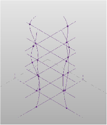
Figure 9.18
Creating several
instances of the
selection and
adding points
9.
The mass is just about complete, and you're ready to load this family into the project.
Open the family file, or if the family is still open, choose the family from the Switch
Windows button on the Quick Access toolbar. When you load an adaptive component