Graphics Programs Reference
In-Depth Information
4.
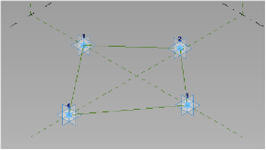
From the Create tab click Reference; then choose the line command. Make sure that 3D
snapping is enabled from the Options bar. Starting with point 1, connect all four of the
reference points to form an enclosed shape (Figure 9.3). Click the Modify button in the
ribbon or press the Esc key twice to quit the Reference Line command.
Figure 9.3
Connecting the four
adaptive points
Now that you have all four points connected forming a rhomboid, you will create a set
of points to round one of the corners of the form. This rounded corner will be associated
with a formula-based parameter so you can modify it within the mass to change its shape.
5.
From the Create tab in the ribbon, click Reference, and choose the Point command. Make
sure you choose the Draw On Face option to the right of the Draw tools. Add two points
on the reference lines to each side of one of the corners. We've added points near corner 3,
as illustrated in Figure 9.4.
Figure 9.4
adding points to
the reference lines
Using points in revit
There are several different types of points in revit, and it's a good idea to know the differences.
in this exercise, we lead you through the creation of several of these point types. Here's a list of
the types and some of their uses:
reference points
These are points that identify a specific X, y, Z location in the conceptual
design environment (adaptive components, conceptual masses, and the like). all reference
points can be tied to parameters.