Graphics Programs Reference
In-Depth Information
Next, the Rotation Angle property of each reference point was associated with the
corresponding family parameter. Point 1 was associated with A1 (angle 1), Point 2 with A2, and
so on.
We then used the Set command in the Work Plane panel to use each point's horizontal
plane as the working reference to draw a square sketch of reference lines associated with each
point. Each sketch was dimensioned in a similar way to the first sketch. The dimensions for
the sketch associated with Point 1 are W1, the Point 2 sketch dimensions are W2, and so on
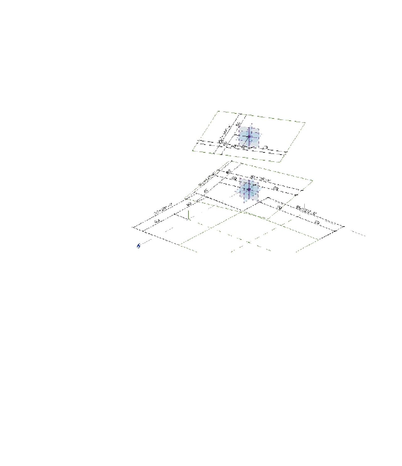
(Figure 8.80).
Figure 8.80
reference line
sketches and
dimensions
For clarity, we've hidden the dimensions in the default 3D view so that you can see all the
reference lines and point elements. If you'd like to see all of the dimensions configured in this
exercise file, activate the 3D view named 3D with Dimensions.
Now let's begin to create some mass forms using the parametrically driven framework of
reference lines in this exercise file. Follow these steps to get started:
1.
While pressing the Ctrl key, select all the square reference line sketches, and then click
Create Form
➢
Solid Form from the Form panel in the ribbon. Although this will look
like a simple extrusion, it's actually a blend with many profiles.
2.
Open the Family Types dialog box and begin to test the results before loading the
family into the project (Figure 8.81). Set the WCPL and APL parameters to
0
and click
Apply.