Graphics Programs Reference
In-Depth Information
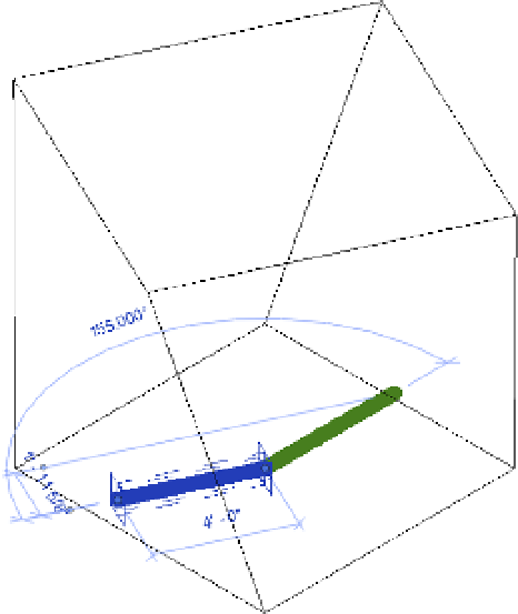
Figure 8.64
Twisting the blend
with reference lines
13.
From a plan view, move the reference lines so that they're no longer on top of the
reference planes. From the Annotate tab, click the Angular dimension tool and place
dimensions between each reference line and the vertical reference plane.
14.
Select the upper angular dimension, and from the Label drop-down list in the Options
bar choose <Add Parameter>. Create a new family parameter with the following values:
◆
Name:
BA
◆
Type or Instance:
Instance
Edit Tooltip:
Bottom angle, counterclockwise from 90
◆
Furthermore, you can add parameters to control the top and bottom angles of the blend.
We've called these instance parameters BA and TA (for bottom angle and top angle,
respectively).
15.
Select the lower angular dimension and again choose <Add Parameter> from the Label
drop-down list. Create another new parameter with the following values:
◆
Name:
TA
◆
Type or Instance:
Instance
Edit Tooltip:
Top angle, clockwise from 270
◆
Figure 8.65 also shows all the parameters that control this blend. From the Create tab
in the ribbon, click the Family Types icon. Go ahead and test the parameter values by
changing angles and clicking the Apply button. The form should rotate and twist. This is
how you will interact with the form after you load it into a project environment.