Graphics Programs Reference
In-Depth Information
1.
Download and open the ile c07-Framing-Start.rvt from the topic's web page. Activate
the Level 1 floor plan.
2.
Switch to the Architecture tab and choose Component
➢
Model In-Place. Set the category
to Structural Framing.
For other scenarios, remember that some categories cannot be cut.
3.
Name the new in-place model
DGN Structure
.
4.
From the Insert tab, select Link CAD.
5.
Change the Files Of Type option to DGN Files (*.dgn) and navigate to the downloaded file.
6.
Set the following options and then click Open:
◆
Current View Only: Unselected
◆
Colors: Black And White
◆
Layers: All
◆
Import Units: Auto
◆
Positioning: Auto - Origin To Origin
◆
Place At: Level 1
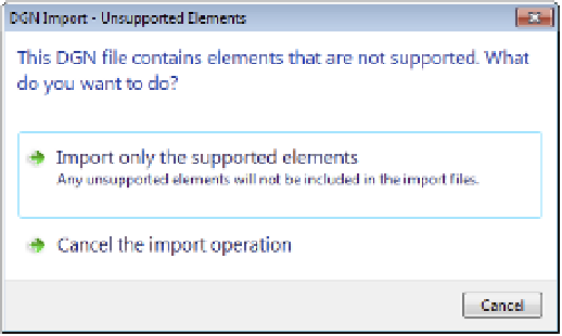
You should receive a warning that the DGN file contains unsupported elements
(Figure 7.15). In this case, simply choose Import Only The Supported Elements and
continue the process.
F igur e 7.15
some Dgn files
may contain
unsupported
elements.
7.
Click Finish Model in the In-Place Editor panel to complete the process.
Switch to a 3D view, and you should see the entire contents of the DGN model (Figure 7.16).
Because the linked content was created as a structural framing model, the linked data will
be displayed similarly to any other structural framing element. Examine the linked model in
different plans and sections to observe this behavior.