Graphics Programs Reference
In-Depth Information
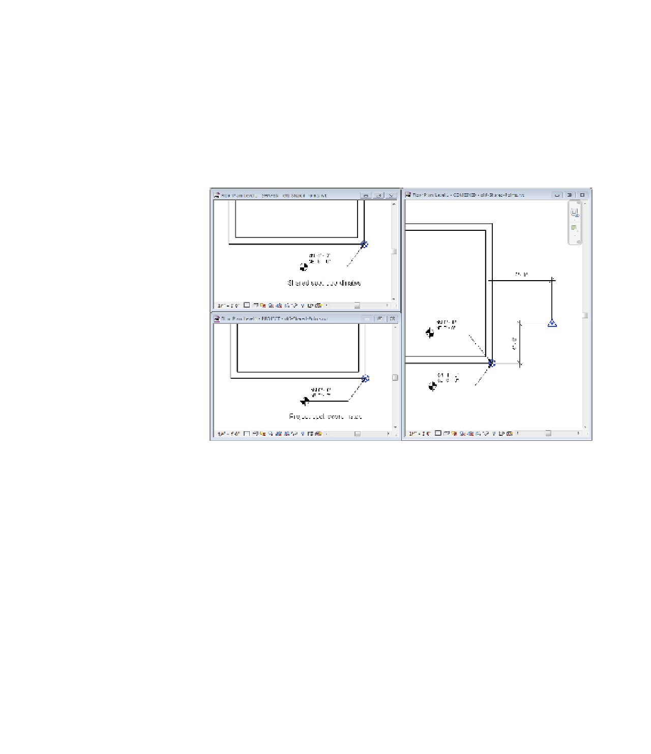
To further expand your understanding of these points and what happens when they are
modified, we have created a sample file for your reference. Open the file c06-Shared-Points
.rvt from this topic's companion web page (
www.sybex.com/go/masteringrevit2015)
. In
this file you will find three copies of the Level 1 floor plan. One view is configured to display the
project coordinates, another view displays the shared coordinates, and the third view displays
a combination of the two. There are also two types of spot coordinates: one indicating project
coordinates in which the values are prefixed with the letter
p
and the other indicating shared
coordinates with the prefix of
s
. You can open these three floor plans and tile the windows (click
the View tab, select the Window panel, and choose Tile, or type the keyboard shortcut
WT
) to get
a better sense of how these points affect one another (Figure 6.8).
Figure 6.8
using tiled
windows helps
you examine the
effect of project
and shared coor-
dinates.
In this sample file, you can explore the effects of moving the Project Base Point and Survey
Point on your model's coordinates. When selected, the Project Base Point and Survey Point
have paperclip icons that determine the behavior of the points when you move them. Clicking
the paperclip icon changes the state from clipped to unclipped and back to clipped.
The following list shows the possible point modifications and explanations of how they
affect the project. In most cases you shouldn't have to move the Survey Point or Project Base
Point if you are using a linked Civil 2D or 3D file and acquiring the coordinates from the
linked file.
Project Base Point: Clipped
◆
Move the PBP (Project Base Point).
◆
PBP values change relative to the Survey Point.
◆
Project-based spot coordinates don't change.
Model elements “move” relative to shared coordinates.
◆