Environmental Engineering Reference
In-Depth Information
j
j+1
dy
j
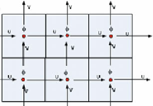
Water level computation point
Flow computation point
dx
i-1
i
i+1
i
Fig. 3.10
Staggered grid schematization for 2D flow simulation [
142
]
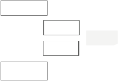
1D channel flow
Open project
Edit model
Time setting
boundary
conditions
Schematization
Setting
Model setting
Schematization
1D 2D overland
flow
Edit user defined
objects
Edit variable for WQ
boundary conditions
View data flow model
Simulation
Results as maps
Results in charts
Results in table
Fig. 3.11
The process modeling in SOBEK (Based on SOBEK manual)


Search WWH ::

Custom Search