Information Technology Reference
In-Depth Information
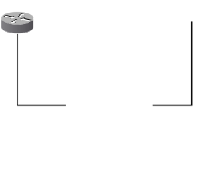
IS-IS Area Layout
Each SONET or SDH ring in the network is typically its own IS-IS L1 area. Figure A-1
shows an example of a four-node ring. The IS-IS adjacencies are shown together with the
level in which they reside.
SONET/SDH Ring with IS-IS Adjacency Information
Figure A-1
R1
R2
L2
L2
L1
L1
NE
L1
L1
GNE
GNE
R3
R4
NE
L1
L1
The connections between the NEs are all L1 adjacencies. The GNE nodes connect to the
gateway routers R3 and R4, which reside in the CO. Using the IS-IS multiarea feature, it is
possible to aggregate a number of rings on the same gateway routers. The gateway routers
connect to the aggregation routers R1 and R2 via L2 IS-IS adjacencies. Typically, 150 gate-
way routers can be terminated on the aggregation routers, depending on the model of router
used for the aggregation routers.
The gateway routers are usually lower-end routers, which is what limits the overall size of
the L2 network to approximately 200 routers. The L1 areas are usually limited to a single
ring per area, or a couple of rings if they are small. This is because of the limited bandwidth
on the DCC for Link State Protocol (LSP) Data Unit flooding.
BGP Peering Relationships
The classic architecture uses only IS-IS, or a combination of IS-IS and static routing, or
ISO-IGRP.
In a BGP architecture, the core network consists of a full iBGP mesh. Route reflectors
can be used if BGP peering scalability is an issue. Confederations are not supported for
CLNS prefix information. The aggregation routers peer with the core network using eBGP.
Figure A-2 shows a sample topology with two COs and a small core network.