Information Technology Reference
In-Depth Information
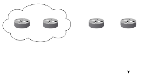
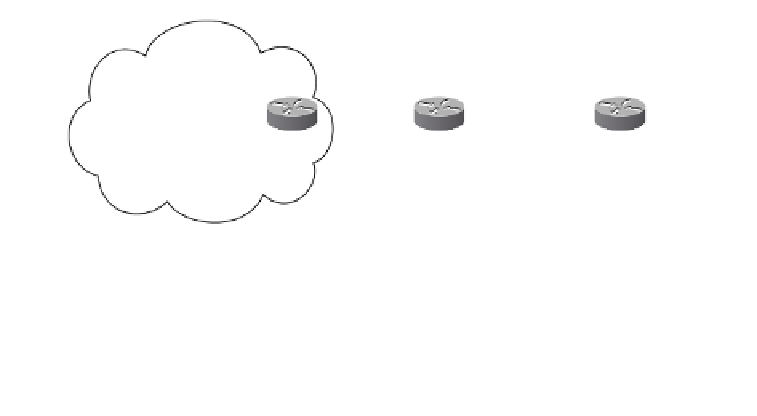
Figure 10-15
Sample Topology for Back-to-Back VRF
AS 200
AS 100
PE1
PE2
PE3
PE4
172.16.0.0/16
AS 65000
AS 65000
VPNa
Site 2
VPNa
Site 1
CE1
CE2
The back-to-back VRF handles the inter-AS VPNv4 connectivity by simply treating the
other ASBR as a CE device. For example, a VRF named VPNa is configured on PE2, with
the link between PE2 and PE3 as part of the VRF. On PE3, the same configuration is made
so as to treat PE2 as a CE.
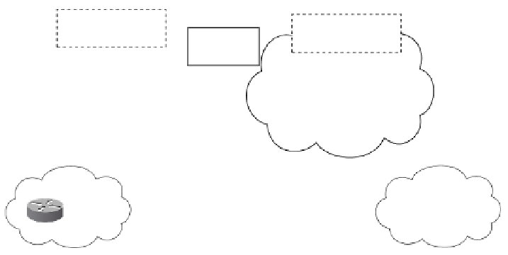
Figure 10-16 shows the VPN prefix and label advertisement. When the prefix 172.16.0.0/16
is advertised from CE2 to PE4, the BGP next hop is set to CE2. The VRF VPNa is config-
ured with an RD of 200:200 and exports an RT of 200:200. When the VPNv4 prefix
200:200:172.16.0.0/16 is advertised toward PE3, the next hop is set to PE4, and an RT
of 200:200 is attached. An in label, Lv1, is assigned for the prefix as well.
Figure 10-16
VPN Prefix and Label Advertisement in Back-to-Back VRF
100:100:172.16.0.0/16
NH=PE2, RT=100:100
Label=Lv2
200:200:172.16.0.0/16
NH=PE4, RT=200:200
Label=Lv1
172.16.0.0/16
NH=PE3
PE1
PE2
PE3
PE4
AS 100
AS 200
172.16.0.0/16
NH=PE1
172.16.0.0/16
NH=CE2
AS 65000
AS 65000
VPNa
Site 1
VPNa
Site 2
CE1
CE2