Information Technology Reference
In-Depth Information
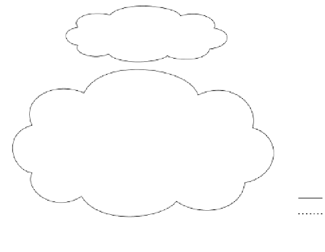
Figure 7-16 is another sample topology, in which two RR client sessions traverse non-
clients. In this example, R5 is an RR that has two clients, R3 and R8. R6 is an RR that has
two clients, R4 and R7. The session between R5 and R8 goes through R7, and the session
between R6 and R7 goes through R8.
Figure 7-16
Persistent Routing Loops
AS 100
R1
R2
172.16.0.0/16
172.16.0.0/16
Client
Client
AS 200
R4
R3
RR
RR
R5
R6
R7
R8
Client
Client
Physical
iBGP
The prefix 172.16.0.0/16 is injected from AS 100 into two border routers in AS 200. Router
R3 advertises the prefix to R5, which in turn reflects to R8 and R6. Assuming that R3 sets
itself as the next hop, which is a common practice, the next hop for this prefix in R8 is R3.
On the other side, R4 does the same thing. Eventually, R7 receives the prefix with the next
hop pointing to R4.
When R8 attempts to forward traffic to the destination of 172.16.0.0/16, it looks up the IGP
next hop to R3, which is R7. Then R8 forwards the traffic to R7. The same thing would
happen in R7, so it would forward the traffic to R8. This forms a persistent routing loop
between R7 and R8. The solutions to this problem are the same as previously discussed:
Make the physical and logical topologies congruent. To follow logical topology, physical
links should be provided between R5 and R6, between R5 and R8, and between R6 and R7.
To follow physical topology, make R7 a client only of R5 and R8 a client only of R6.