Environmental Engineering Reference
In-Depth Information
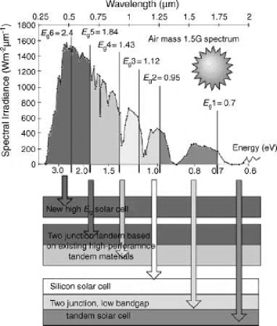
Figure 7.16 Schematic [96] of the
multijunction solar cell grouping for the
lateral
architecture.
Upper panel shows the authors
version of the
AM 1.5 G
spectrum (see also
Figure 5.2) with the authors
division of the
spectrum into six ranges, indicating an
optimum single-junction bandgap for each
range. (Not shown, a semicylindrical dichroic
lens system giving laterally displaced focal
points for different wavelengths. The authors
also mention arrays of these junction devices.)
7.3
Spectral Splitting Cells
A more elaborate, and surely more expensive, approach to multiple junctions has
been described by Barnett et al. (see Figure 7.16) [96].
The new method involves splitting, by dispersive optics, the incoming light into
bins of high energy, mid energy, and low energy. (In principle, the triangular glass
prism of Isaac Newton would serve this purpose, and it appears that the ef
ciency of
such optical devices can exceed 90%. In this case, a focusing action is also
incorporated, to provide concentration of the light.) Light in each energy range is
directed by such a lateral optical system to an appropriate, possibly multijunction,
solar cell. In the schematic of Figure 7.16, two of the photon energy ranges are
converted with tandem junction devices.
The same group reported [97] a record 42.8% ef
ciency for revised version of
this lateral optical system approach, apparently involving
five or six junctions in