Environmental Engineering Reference
In-Depth Information
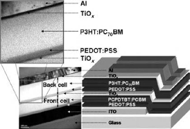
Figure 7.9 (Right) Schematic [92] of tandem
polymer organic solar cell structure with
efficiency over 6%. The structure consists of two
cells (front and back) in series, separated by a
transparent titanium oxide (TiO
x
) layer. Each
constituent cell is of the type shown in Figure
6.10, right panel, except that the charge-
separating heterojunctions are distributed as a
bulk heterojunction composite
in the dye-
fullerene layers (1st and 3D from top, in the
schematic diagram). Here, PEDOT:PSS is a
highly conductive hole transport layer and ITO is
conductive indium tin oxide. The
P3HT
fullerene layers
are the active charge separation layers, each
described as a
bulk heterojunction composite
of a dye polymer donor with the fullerene
acceptor. (Left, upper and lower) TEM cross-
sectional images of portions of the structure.
Note the sharp interfaces, and scale bars 20 nm
(upper) and 100 nm (lower).
-
fullerene and PCPDTBT
-
Light enters through the glass
-
ITO substrate into the front cell at the bottom.
Absorption and charge separation in the front cell (PCPDTBT
-
fullerene) is strong in
the UVand in the IR, but most of the visible spectrumpasses through. The back cell
(P3HT
-
fullerene) absorbs and charge-separates the visible portion of the spectrum.
Thus, the two junctions harvest complementary portions of the solar spectrum.
Because the cells are in series, and the electrical current is constant through the cell,
the short-circuit current of the tandemcell is limited to the smaller of the short-circuit
currents of the constituent cells.
In each cell, referring to right panel of Figure 7.9, photoelectrons
flow vertically
upward through the fullerene network of each composite and into the electron-
conductive TiO
x
layers. For the back cell (top of
figure), these electrons go through
the aluminum
lm into the external load. For the front cell the photoelectrons
annihilate with holes at the interface of the TiO
x
and the upper, hole-conducting
PEDOT:PSS layer, which is fed photoholes from the (upper) back cell. The
annihilation of electrons and holes at the TiO
x
-
PEDOT:PSS interface makes the
current continuous through the device. (The TiO
x
layer will not transmit holes from
the back cell into the front cell because its valence band energy,
8 eV relative to
vacuum, is too low for holes to enter.) Photoholes generated in the front cell (lower)
ow down through the lower PEDOT:PSS hole-conducting layer and annihilate at the