Environmental Engineering Reference
In-Depth Information
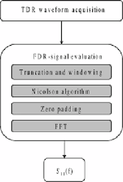
Fig. 3.9
Schematic diagram
illustrating the algorithm
for the TD/FD combined
approach and for extrapolat-
ing the reflection scattering
parameter from TDR mea-
surements
where
er f
is the error function,
α
t
is the inverse of the rise time of the step-like
signal, and
t
0
is the position where the input signal starts the rise. The parameter
α
t
is evaluated by fitting the
v
0
,
art
(
to the TDR waveform of the probe in air [29].
As will be seen later, the adoption of the SOL calibration on FD-transformed
TDR measurements can help circumventing the need of evaluating
v
0
(
t
)
t
)
.
3.5
The Sensing Element
The sensing element (or probe) is responsible for the interaction of the stimulus sig-
nal with the SUT, and it is the ultimate factor that influences the accuracy of results.
Since microwave reflectometry senses the changes in impedance, it is extremely im-
portant to employ a probe with a well-known impedance profile; in this way, it is
easier to discriminate and interpret the impedance variations due to the SUT.
The high versatility of microwave reflectometry is also related to the possibility
of customizing the probe configuration, thus employing an ad hoc solution for the
specific needs.
Coaxial probes, which are widely used for monitoring and diagnostics on liquids,
are the most simple to design. A coaxial probe is composed of an outer cylinder
(acting as the outer conductor) and a rod along the center line of the cylinder (acting
as a central conductor). The impedance profile (in the TEM propagation mode) can
be easily determined from the transmission line theory, as reported in Sect. 2.1 [21,
25]:
60
Z
(
f
)=
ln
(
b
/
a
)
(3.14)
ε
(
f
)
r
where
Z
is the frequency-dependent impedance of the probe filled with the con-
sidered material;
(
f
)
ε
r
(
f
)
is the relative dielectric permittivity of the material filling the


Search WWH ::

Custom Search