Environmental Engineering Reference
In-Depth Information
Ta b l e 2 . 1
Typical parameters used for describing electrical networks
symbol matrix
ABCD
∗
transmission
Z impedance
Y admittance
H
∗
hybrid
G
∗
inverse hybrid
S scattering
∗
Cannot be used for networks with more than 2 ports.
At high frequencies, the influence of parasitics (i.e., capacitances, cable induc-
tance, undesired coupling effects) becomes more significant; hence, it becomes in-
creasingly difficult to measure voltages and currents. In this case, it is preferred to
measure power, and if necessary, to successively extrapolate the other parameters of
interest. In this regard, scattering parameters (
S-parameters
) are particularly conve-
nient; in fact,
S-parameters
relate to signal flow rather than to voltages and currents
directly. In particular, the 'measured quantities' are traveling waves.
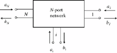
Fig. 2.6
Schematization of
an
N
-port network
Considering an
N
-port network (Fig. 2.6), scattering variables at the generic port
n
are defined in terms of the port voltage
V
n
, port current
I
n
, and a normalization
impedance
Z
0
. The voltage and the current can be synthesized by an incident scat-
tering variable,
a
n
, and a reflected scattering variable
b
n
,givenby
I
n
√
Z
0
2
V
n
2
√
Z
0
+
a
n
=
,
(2.22)
I
n
√
Z
0
2
V
n
2
√
Z
0
−
b
n
=
.
(2.23)
The scattering parameters are measured in terms of
a
n
and
b
n
.Fora
N
-port network,
there are
N
2
scattering parameters,
S
ij
, with
i
,
j
=
1
, ...,
N
.
j
are referred to as reflection scattering parameters.
They are practically measured as the ratio between the outgoing and incoming wave
The
S-parameters
where
i
=


Search WWH ::

Custom Search