Environmental Engineering Reference
In-Depth Information
(a)
(b)
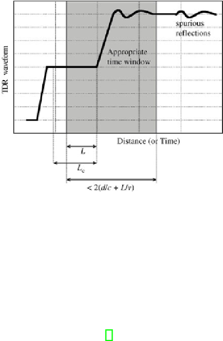
Fig. 6.2 a
Schematization of a typical TDR waveform.
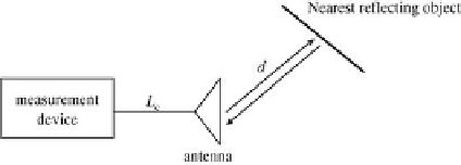
b
schematization of possible interfer-
ences from the environment [5]
6.4
RFId Antenna Results
The configuration of the Alien ALR-8610-AC antenna antenna is shown in Fig.
6.1(a). The truncated edge-geometry of this antenna (highlighted with circles in the
figure) is realized to guarantee circular polarization with only one feed point and
to generate two closely-spaced resonant frequencies, between which the antenna
should operate [12].
The antenna was connected to the TDR module through a 28 cm-long LMR195
cable with a nominal impedance of 50
. It is worth underlining an important as-
pect on the feed of this antenna under test (AUT). The terminal part of the central
conductor of the coaxial cable that feeds the antenna is not surrounded either by
dielectric insulator or by external jacket: this introduces an additional impedance
mismatch (between the 50
Ω
Ω
-cable and the antenna) that inevitably affects the TDR
response of the antenna [1].


Search WWH ::

Custom Search