Environmental Engineering Reference
In-Depth Information
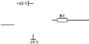
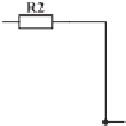
Figure 1.35
Typical signal conditioning circuits
offers a low output impedance to the analog inputs. The op-amp also isolates the ADC and
protects the ADC inputs.
Figure 1.35(a) shows a typical voltage follower implemented with op-amp TL072. It is
particularly suitable for cases where the output voltage from a sensor is already in the right
range, e.g. 0
∼
3 V for DSP, but the impedance on both sides do not match.
1.3.5.2 Scaling and Level-shifting
If the voltage range of a signal from a sensor is not within the right range of the analog inputs,
then the signal needs to be scaled and often shifted as well. In this case, the circuit shown in
Figure 1.35(b) can be used. It consists of two stages: the first stage to scale (i.e. to amplify or
attenuate) the signal
V
s
to the range of
−
3V
∼
3 V and the second stage to scale and shift it
to 0
∼
3 V. The relationship between the input
V
s
and the output
V
i
is
R
7
R
4
×
R
2
R
1
×
R
4
+
R
7
R
6
V
i
=
V
s
+
×
R
5
×
V
REF
.
(1.5)
R
4
R
6
+
If
R
4
=
R
5 and
R
6
=
R
7, then
R
7
R
4
(
V
REF
+
R
2
R
1
×
V
i
=
V
s
)
.


Search WWH ::

Custom Search