Environmental Engineering Reference
In-Depth Information
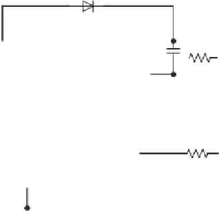
Figure 1.28
Typical connection of IR2130.
Source:
IR 2004
referenced output channels (IR 2004). IR2110 is suitable for one phase leg and IR2130 is
suitable for three phase legs. Figure 1.28 shows the typical connection of IR2130 (IR 2004).
Proprietary HVIC technology enables ruggedised monolithic construction. The logic inputs
are compatible with CMOS or LSTTL outputs, down to 2.5 V logic. A ground-referenced
operational amplifier provides analog feedback of the bridge current via an external current-
sensing resistor, from
which a
current trip function that terminates all six outputs is also
derived. An open drain FAULT signal is provided to indicate that an over-current or under-
voltage shutdown has occurred. The output drivers feature a high pulse current buffer stage
designed for the minimumdriver cross-conduction. Propagation delays are matched to simplify
use at high frequencies. The floating channels can be used to drive N-channel power MOSFETs
or IGBTs in the high side configuration, which operate up to 600V.
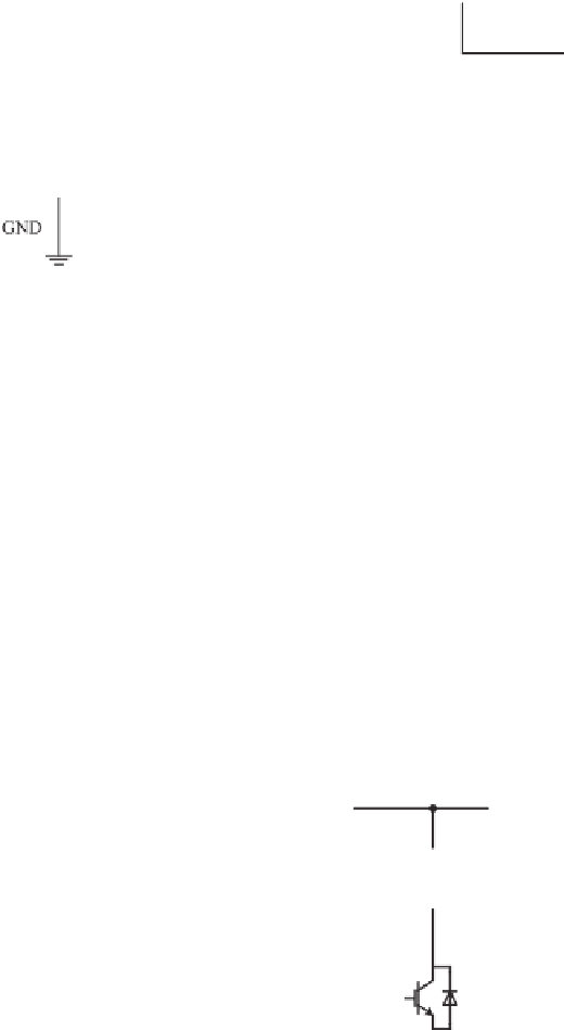
Figure 1.29 shows a typical connection of the driving signal to the gate of an IGBT. In order
to weaken the influence of the Miller capacitance and the stray inductance, turn-on and turn-off
Figure 1.29
Typical connection between the gate and the emitter of an IGBT


Search WWH ::

Custom Search