Environmental Engineering Reference
In-Depth Information
Table 1.1
Operational logic of the TLP550 shown in Figure 1.25
PWM_DSP
PWM Output transistor
PWM_Drive
IGBT
1
1
OFF
1
OFF
0
0
ON
0
ON
High-Impedance State
1
OFF
1
OFF
It is worth noting that efforts should be made to minimise the difference between the driving
channels, in particular, the channels for the switches on the same leg, because of the high
speed of operation.
1.3.2 Power Stages
Power stages are the key part of an inverter system and are responsible for power transfer and
conversion. Proper design and selection of power modules and the associated auxiliary circuits
are crucial for the normal operation, reliability, lifetime and efficiency of the inverter.
1.3.2.1 Power Modules
With the development of power semiconductor technologies, power switches have experienced
several stages. At present, discrete IGBT/MOSFET components and power modules built with
IGBTs are commonly used in inverters. These devices are fully on-off controllable and are
ideal for inverters.
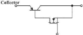
Figure 1.26 shows the equivalent circuit of an ideal IGBT, which is the combination of a
power transistor and a MOSFET. As a result, an IGBT combines the advantages of transistors
(low conduction loss) and MOSFET (high-speed turn-on and easy drive with a low-power
voltage signal). When a positive voltage is applied between the gate and the emitter, the
MOSFET is turned on and hence the transistor is on. When the voltage is removed, the
MOSFET is off and hence the transistor is off.
The current and voltage ratings of the IGBTs in an inverter should be selected appropriately
to meet the requirements on the power and voltage levels. Moreover, discrete IGBT mod-
ules should be protected from over-currents, over-voltages, over-heating, etc. Because of the
losses, heat sinks are often needed and should be designed appropriately to keep the junction
temperature of the IGBT module below the maximum allowable value. Some guidelines can
often be found in the product manuals, e.g. (FUJI 2004).
Figure 1.26
Equivalent circuit of an IGBT


Search WWH ::

Custom Search