Environmental Engineering Reference
In-Depth Information
i
in
Q
1
Q
3
V
DC
2
i
o
a
L
N
C
v
o
b
V
DC
2
Q
4
Q
2
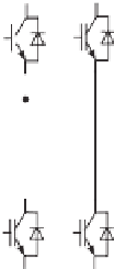
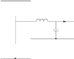
Figure 1.19
Single-phase voltage-source inverter
1.2.3.2 Operation of Single-phase Inverters
Figure 1.19 shows a single-phase inverter with a DC voltage source. The DC bus voltage is
split into two halves to illustrate the operation of the inverter and the mid-point of the DC bus
is the reference point for the two phase legs.
The inverter can be operated to obtain bipolar and unipolar SPWM signals for
v
ab
. When
it is operated with the unipolar SPWM signal shown in the right column of Figure 1.17, the
voltages
v
o
are shown in the left column of Figure 1.20. In
this case, phase-leg
a
is operated according to the unipolar SPWM signal and phase-leg
b
is
operated according to the polarity of the voltage signal at its frequency. For example, when the
modulating voltage
u
is positive,
Q
1
and
Q
4
are turned ON and OFF according to the unipolar
SPWM signal while
Q
2
is always ON and
Q
3
is always OFF; when
u
is negative,
Q
1
and
Q
4
are turned ON and OFF according to the SPWM signal while
Q
2
is always OFF and
Q
3
is
always ON. This is able to reduce switching losses because the second leg is operated at the
frequency of the voltage.
It is possible to operate the inverter to obtain a unipolar SPWM for
v
aN
,
v
bN
, together with
v
ab
and
v
ab
although the phase
legs are driven by bipolar SPWM signals, as shown in the right column of Figure 1.20. In this
case, the modulating voltage
u
and its opposite
u
are compared with the carrier waveform
to generate two sets of bipolar SPWM signals to drive the two phase legs. As a result, the
voltages
−
v
bN
are 180
◦
apart from each other. The voltage
v
aN
and
v
ab
, which is the difference
v
bN
, is unipolar at the doubled switching frequency. Since both
phase legs are operated at the same high switching frequency, the switching losses are high
but because the resulting
v
aN
and
of the two voltages
v
ab
has a doubled switching frequency, the output voltage quality is
better than the case shown in the left column of Figure 1.20. In this case, the two phase legs
are operated as two separate phases, which are 180
◦
apart from each other.
When both legs of the inverter are operated with the bipolar SPWM shown in the left column
of Figure 1.17, the resulting curves are shown in Figure 1.21. In this case, the same SPWM
signal is sent to the two phase legs in a complementary way. That is,
Q
1
and
Q
2
are operated
as a pair at the same time and
Q
3
and
Q
4
are operated as a pair at the same time. As a result,
v
bN
=−
v
aN
and
v
aN
.
Note that the amplitude of
v
ab
=
2
V
DC
for all three different operation modes and the
maximum achievable amplitude is the same as the DC bus voltage.
v
ab
is
±


Search WWH ::

Custom Search