Environmental Engineering Reference
In-Depth Information
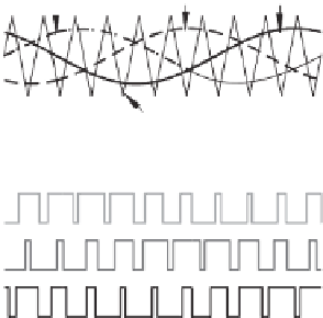
Modulating signal
Carrier
Modulating signal
Carrier
(a) Sketch of modulation
(b) Gate signal for the upper switch
(c) Gate signal for the lower switch
Figure 1.17
Sinusoidal PWM for a single-phase inverter: Bipolar (left column) and unipolar (right
column)
RMS value of the output voltage. As a result, the amplitude and frequency of the output voltage
can easily be changed by controlling the modulating signal. Because the carrier changes its
sign during the positive or negative half cycle, this SPWM is bipolar. If the carrier does not
change its sign during the positive or negative half cycle, then the resulting SPWM is unipolar,
as shown in the right column of Figure 1.17. Note that in both cases, the upper switch and the
lower switch on the same leg are operated in a complementary way.
Similarly, for three-phase applications, three modulating signals can be compared with the
carrier signal to generate the gate-driving signals, as shown in Figure 1.18.
v
a
v
b
v
c
Carrier
(a) Sketch of modulation
(b) Three-phase SPWM gate signals (for upper switches)
Figure 1.18
Sinusoidal PWM for a three-phase inverter


Search WWH ::

Custom Search