Environmental Engineering Reference
In-Depth Information
αβ
θ
θ
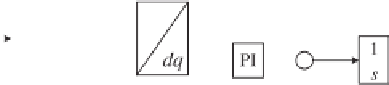
Figure 22.4
Typical structure of a single-phase PLL
The SRF-PLL is popular and widely applied in power control applications. It is also available
in MATLAB
R
/Simulink
R
SimPowerSystems
TM
blocksets. In the ideal balanced condition,
the SRF-PLL is able to eliminate the steady state error in tracking the phase and frequency and
to achieve high bandwidth, which delivers fast and accurate tracking performance. However,
it is very sensitive to harmonics or imbalance in the voltage and improved control schemes are
necessary in these applications (Escobar
et al
. 2011; Rodriguez
et al
. 2007a, 2007b).
The SRF-PLL concept can also be applied to single-phase applications although there are
no three balanced voltages available and an instantaneous single-phase voltage
v
cannot be
transformed into a space vector as is done in three-phase systems (Shinnaka 2008). The idea
(Ciobotaru
et al
. 2006; Shinnaka 2008; Yuan
et al
. 2002) is to generate two perpendicular
components
e
and
e
q
and then treat these two components as
v
α
and
v
β
to form
v
αβ
to be used
in (22.3). The component
e
is the estimated version of
and the component
e
q
is a quadrature
component, that is 90
◦
shifted from
e
. The resulting single-phase PLL is sketched in Figure
22.4. The second-order generalised integrator (SOGI) to be described in detail in the next
section is one way to generate the two perpendicular components
e
and
e
q
. It is worth noting
that there are other single-phase synchronisation methods that are not based on the generation
of a quadrature signal too; see e.g. (da Silva
et al
. 2010; Freijedo
et al
. 2011; Mojiri
et al
.
2007).
v
22.5 Second-order Generalised Integrator-based PLL (SOGI-PLL)
As mentioned above, if two perpendicular components
e
and
e
q
are generated from a single-
phase voltage
v
β
to further obtain
two DC components
V
d
and
V
q
. The simplest way is to use a transport delay block or a lag
compensator to shift the input signal
v
, then these two components can be treated as
v
α
and
90
◦
. However, this method suffers from high
sensitivity to frequency variations and harmonics, which makes the DC components polluted
(Ciobotaru
et al
. 2006).
The SOGI is able to generate both in-phase
e
and quadrature
e
q
components that are
filtered and contain only the fundamental component. This is referred to as the SOGI-based
quadrature-signal generator (SOGI-QSG) (Yuan
et al
. 2002). It consists of feedback loops
involving two integrators, as shown in Figure 22.5(a). The transfer function
G
d
(
s
) from
v
by
−
v
to
e
is
k
ω
s
G
d
(
s
)
=
2
,
(22.5)
s
2
+
k
ω
s
+
ω


Search WWH ::

Custom Search