Environmental Engineering Reference
In-Depth Information
the output of the PD, is driven to zero eventually. As a result, the phase of the output signal is
locked with that of the input signal.
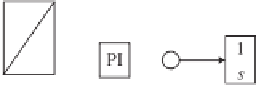
Figure 22.2(b) shows the control structure of a simple PLL, where the PD unit is a multiplier,
the LF is a low-pass filter (LPF) and the VCO consists of a PI controller, an integrator and
a sinusoidal function. For an input signal
v
=
V
m
cos
θ
g
with phase
θ
g
=
ω
g
t
+
φ
g
and an
output signal
y
=
sin
θ
with phase
θ
=
ω
t
+
φ
, the output of the PD unit is
v
=
v
y
=
V
m
sin
θ
cos
θ
g
V
m
2
V
m
2
=
sin(
θ
−
θ
g
)
+
sin(
θ
+
θ
g
)
.
(22.1)
V
m
2
The
two
components
in
(22.1)
can
be
rewritten
as
sin[(
ω
−
ω
g
)
t
+
(
φ
−
φ
g
)]
and
V
m
2
φ
+
φ
g
)]. It is obvious that the first term is a low frequency component
that contains the phase difference between
sin[(
ω
+
ω
g
)
t
+
(
and
y
and the second term is a high frequency
component, which is out of interest and can be filtered out with the loop filter. The output
d
of
the LF is
v
V
m
2
d
=
sin[(
ω
−
ω
g
)
t
+
(
φ
−
φ
g
)]
,
˙
ω
=
θ
=
which is then fed into a PI controller to generate the estimated frequency
until
d
0.
=
θ
The estimated frequency is integrated to form the phase of the output signal
y
, which
is sent back to the PD unit to complete the loop. In the steady state,
d
is driven to zero and
θ
=
θ
g
, i.e.
sin
ω
=
ω
g
and
φ
=
φ
g
. The phase of the output signal
y
is said to be locked with
that of the input signal
.
It is worth noting that the input signal and the output signal are actually 90
◦
shifted in order
for the DC component
d
to be zero when
v
is a cosine
curve and
y
is a sine curve. This is not a problem because a constant can be added to
θ
=
θ
g
. Indeed, in the case shown here,
v
θ
to
obtain any phase angle needed.
22.4 PLL in the Synchronously Rotating Reference Frame (SRF-PLL)
A common technique in three-phase applications is a PLL in the synchronously rotating
reference frame (SRF-PLL) (Amuda
et al
. 2000; da Silva
et al
. 2010; Kaura and Blasko 1997),
which is shown in Figure 22.3. Similar operating concepts can also be found, e.g. in (Chung
2000).
αβ
θ
αβ
θ
θ
αβ
Figure 22.3
Three-phase PLL in the synchronously rotating reference frame (SRF-PLL)


Search WWH ::

Custom Search