Environmental Engineering Reference
In-Depth Information
L
i
L
D
i
o
v
L
-
+
+
i
c
+
Q
v
s
C
Load
v
o
-
-
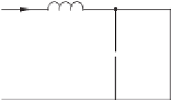
(a) Topology
L
L
i
L
i
o
i
L
i
o
+
v
L
-
v
L
-
+
+
+
i
c
i
c
+
+
Load
v
o
v
s
C
Load
v
o
v
s
C
-
-
-
-
(b) Mode 1 (Q: ON)
(c) Mode 2 (Q: OFF)
0
0
kT
T
(k+1)T
kT
T
(k+1)T
Time
Time
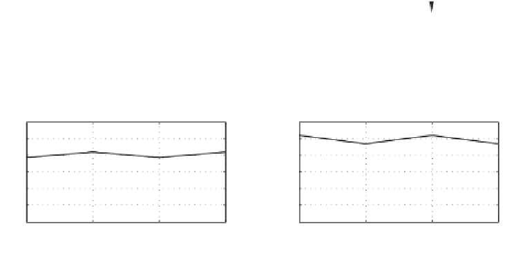
(d) Inductor current
(e) Capacitor voltage
Figure 1.15
Typical boost converter
source are transferred to the load and the capacitor. The inductor current decreases linearly
because
L
d
i
L
d
t
=
v
s
−
v
o
.
Similarly, the net energy changed in the inductor should be zero during one period in the steady
state, which means the current increased in Mode 1 should be equal to the current decreased
in Mode 2. That is,
kT
L
v
s
=
(1
−
k
)
T
L
(
v
o
−
v
s
)
,
from which the output voltage can be derived as
1
v
o
=
k
v
s
.
1
−


Search WWH ::

Custom Search