Environmental Engineering Reference
In-Depth Information
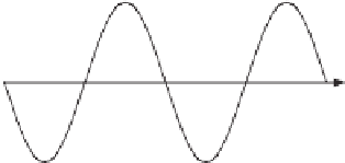
Figure 22.1
Zero-crossing method
to be constant in at least one half cycle, which is not always true. The method is thus very
vulnerable to phase jumps, when large loads are switched on and off, and to variations in the
grid frequency. Another problem is the multiple zero-crossing that could happen when the
input signal is distorted by harmonic components (Wang and Li 2011a). The detection could
also be affected by the bias in the analog to digital converter (ADC) or the comparator circuit
and hence the system should be well calibrated.
22.3 Basic Phase-locked Loops (PLL)
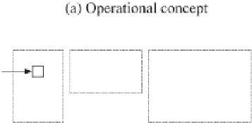
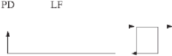
The block diagram to demonstrate the operating concept of a PLL is shown in Figure 22.2(a).
It consists of a phase (error) detection (PD) unit, a loop filter (LF) and a voltage controlled
oscillator (VCO). The PD unit measures the phase difference between the input signal and the
reproduced output signal and then passes it through the loop filter to extract the DC component
obtained from the phase error. The DC component is amplified and then passed to the VCO,
which could be a PI controller to generate the frequency of the output signal. The frequency is
integrated to form the phase of the output signal. If the frequency of the output signal is locked
with the input frequency, then the phase difference between the input and output signals, i.e.
θ
θ
Figure 22.2
Block diagrams of a conventional PLL


Search WWH ::

Custom Search