Environmental Engineering Reference
In-Depth Information
120
120
i
1
i
2
i
1
i
2
80
80
40
40
0
0
−40
−40
−80
−80
1.54
1.55
1.56
1.57
1.58
1.59
1.6
1.54
1.55
1.56
1.57
1.58
1.59
1.6
Time [s]
Time [s]
(a) Currents
400
400
200
200
0
0
−200
−200
−400
−400
1.54
1.55
1.56
1.57
1.58
1.59
1.6
1.54
1.55
1.56
1.57
1.58
1.59
1.6
Time [s]
Time [s]
(b) Output voltage
20
20
16
16
THD=17.7%
THD=9.77%
12
12
8
8
4
4
0
0
1
3
5
7
9
11
13
15
17
19
1
3
5
7
9
11
13
15
17
19
Harmonic order
Harmonic order
(c) Magnitude of the harmonic voltages w.r.t. the fundamental component
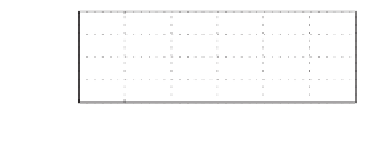
Figure 21.7
Simulation results for a 230 V system: without the harmonic droop controller (left column)
and with a 3rd and 5th harmonics droop controller (right column)
of the rated voltage and power. The coefficients
n
h
were also scaled, correspondingly, to
n
h
=
5
×
12
230
(
12
230
)
2
1361. The simulation results are shown in
Figure 21.7. Again, the THD of the voltage was significantly improved by 45%, from 17
=
0
.
2609 and
m
h
=
50
×
=
0
.
.
7%
to 9
77%. The third harmonics was reduced from 16% to 5% but the 5th harmonics in-
creased slightly.
.
21.5 Experimental Results
Experiments were carried out with a laboratory set-up, which consisted of two single-phase
inverters controlled by dSPACE ACE1104 kits and was powered by separate 42 VDC power
supplies. The parameters of the inverters are the same as those in the simulations for the
12 V system. The switching/sampling frequency was set at 4 kHz because of the hardware
limitation, partially caused by the heavy computation involved in calculating the real power
and reactive power at each frequency. Due to the configuration of the hardware set-up, the
voltage of Inverter 2 was measured by the controller of Inverter 1 and then sent out via a DAC
channel, which was then sampled by the controller of Inverter 2. This brought some latency
into the system. The voltages were measured through a multiplexer, which resulted in a much
lower sampling frequency for the voltage. This may have had an impact on the performance.
Inverter 2 was equipped with a synchronisation unit. It was synchronised with Inverter 1 when
its output was not connected to that of Inverter 1 so it was ready to be connected at any time.


Search WWH ::

Custom Search