Environmental Engineering Reference
In-Depth Information
Table 21.1
Voltage THD
Switching/sampling frequency
20 kHz
10 kHz
4 kHz
Voltage THD with the strategy
9.03%
9.4%
14.4%
Voltage THD without the strategy
16.53%
16.5%
20%
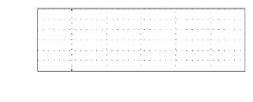
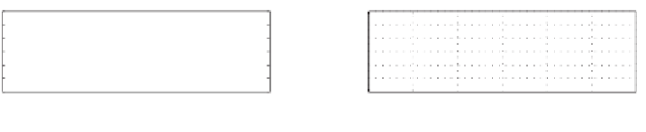
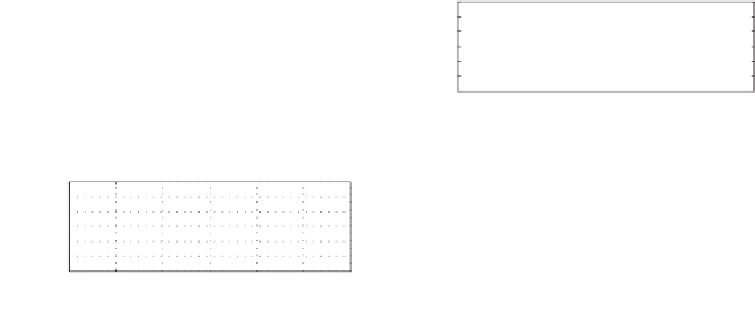
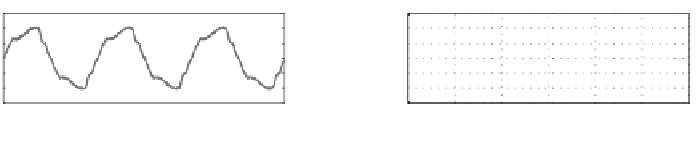
inverter currents when the switching frequency was 20 kHz are shown in Figure 21.6. The 3rd
harmonics was significantly reduced from 15% to 5% but the 5th harmonics slightly increased
because of the change in the current profile caused by the reduction of the third harmonics.
The two inverters shared the real power and reactive power well in the ratio of 2:1 and the
voltage was maintained close to the rated voltage.
Another system consisting of two inverters rated at 230 V 50 Hz were simulated to show the
scalability of the strategy. The parameters of the LC filters and the load were not changed (but
with higher current and voltage ratings). The power consumed was around 8 kVA with a power
factor of 0.9. The gains of the inner loops were kept the same as well but the fundamental droop
coefficients were scaled to
n
1
=
2
.
2
×
12
230
(
12
230
)
2
10
−
4
for
=
0
.
1148 and
m
1
=
0
.
14
×
=
3
.
811
×
10
−
4
Inverter 1 and
n
1
=
0
.
0574 and
m
1
=
1
.
9055
×
for Inverter 2 because of the change
−
−
−
6
−
−
−
6
i
1
i
2
i
1
i
2
0.94
0.95
0.96
0.97
0.98
0.99
1
0.94
0.95
0.96
0.97
0.98
0.99
1
Time [s]
Time [s]
(a) Currents
1
24
1
24
−1
−
8
−1
−
8
−24
−24
0.94
0.95
0.96
0.97
0.98
0.99
1
0.94
0.95
0.96
0.97
0.98
0.99
1
Time [s]
Time [s]
(b) Output voltage
20
20
16
16
THD=16.53%
THD=9.03%
12
12
8
8
4
4
0
0
1
3
5
7
9
11
13
15
17
19
1
3
5
7
9
11
13
15
17
19
Harmonic order
Harmonic order
(c) Magnitude of the harmonic voltages w.r.t. the fundamental component
Figure 21.6
Simulation results for a 12 V system: without the harmonic droop controller (left column)
and with a 3rd and 5th harmonics droop controller (right column)


Search WWH ::

Custom Search