Environmental Engineering Reference
In-Depth Information
Z
Load/grid
i
o
v
~
o
i
i
h
v
…
…
~
↓
↓
v
r
o
v
~
oh
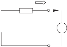
(a) One circuit including all harmonics
S
=
P
+
Q
h
h
h
i
h
*
Z
o
(
jh
ω
)
~
~
↓
v
i
v
rh
h
oh
(b) The circuit at the
h
-th harmonic frequency
Figure 21.1
Model of an inverter connected to a load/grid in terms of harmonic voltage and current
sources
v
o
1
=
√
2
V
o
1
sin(
v
oh
=
√
2
V
oh
sin(
h
ω
∗
is the rated funda-
mental angular frequency of the system,
V
o
1
is the RMS value of the fundamental component
and
V
oh
is the RMS value of the
h
-th harmonic component. The output or load current is
described as
ω
∗
t
) and
ω
∗
t
with
+
ψ
h
), where
=
h
=
1
i
h
,
i
with
i
h
=
√
2
I
h
sin(
h
ω
∗
t
+
φ
h
). This represents the effect of non-linear loads or harmonic
currents and forces the current flowing through the series of voltage sources to be zero. The
voltage reference
v
r
in the general case is described as
v
r
=
v
r
1
+
h
=
2
v
rh
v
r
1
=
√
2
E
sin(
v
rh
=
√
2
E
h
sin(
h
ω
∗
t
ω
∗
t
with
+
δ
h
). In many cases, in particular,
when a droop controller is used in the inverter,
E
h
is often set to be zero. In this chapter,
E
h
is
set to be non-zero to make
+
δ
) and
v
oh
close to zero.
This circuit can be analysed after decomposing it into multiple circuits at each harmonic
frequency, according to the superposition theorem. The
h
-th harmonic circuit of the system


Search WWH ::

Custom Search