Environmental Engineering Reference
In-Depth Information
28
2
24
P
1
P
2
Q
1
Q
2
0
20
−2
16
−4
12
−6
8
−8
4
−10
0
−4
−12
0
1
2
3
4
5
6
7
8
9
10
11
12
0
1
2
3
4
5
6
7
8
9
10
11
12
Time [s]
Time [s]
(a) Active power
(b) Reactive power
28
10
9
E
1
E
2
24
20
16
5
12
8
2
4
0
0
1
2
3
4
5
6
7
8
9
10
11
12
0
1
2
3
4
5
6
7
8
9
10
11
12
Time [s]
Time [s]
(c) Voltage set-point
(d) THD of the output voltage
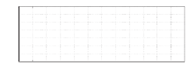
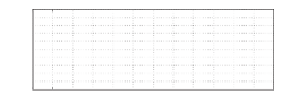
Figure 20.14
Experimental results at 2 : 1 power sharing when the non-linear load was changed
Figure 20.14 shows the effect of changing the nonlinear load. The resistance of the load was
changed from 5
8 s. The inverters
shared the load in the ratio of 2 : 1 during the process and the voltage THD reduced below 5%
when the load was decreased.
.
7
to 7
.
9
at
t
=
3
.
8 s and then changed back at
t
=
8
.
20.3 Summary
Based on (Zhong 2012c; Zhong
et al
. 2011, 2012), the control strategies presented in Chapters 8
and 19 are combined to improve the voltage quality of parallel operated inverters that are able
to share the real power and reactive power accurately and to regulate the output voltage
well. Extensive experimental results are presented to demonstrate that the combined compact
controller is able to achieve accurate power sharing, low THD and excellent voltage regulation
at the same time.


Search WWH ::

Custom Search