Environmental Engineering Reference
In-Depth Information
28
2
P
1
P
2
Q
1
Q
2
24
1
20
0
16
12
−1
8
−2
4
−3
0
−4
−4
0
1
2
3
4
5
6
7
8
9
10
11
12
0
1
2
3
4
5
6
7
8
9
10
11
12
Time [s]
Time [s]
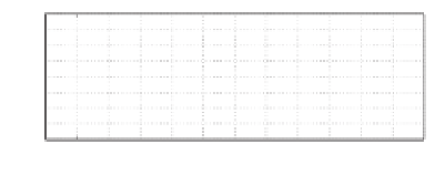
(a) Active power
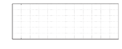
(b) Reactive power
28
10
E
1
E
2
9
24
20
16
5
12
8
4
1
0
0
1
2
3
4
5
6
7
8
9
10
11
12
0
1
2
3
4
5
6
7
8
9
10
11
12
Time [s]
Time [s]
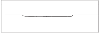
(c) Voltage set-point
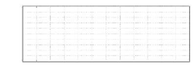
(d) THD of the output voltage
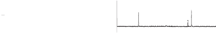
Figure 20.12
Experimental results at 2 : 1 power sharing when the linear load was changed
20.2.2.2 With a Linear Load
A linear load of about 7
.
9
was connected to Inverter 2 initially. Inverter 1 was connected
=
.
=
to the system at
t
10 s. The relevant curves of the
experiment are shown in the left column of Figure 20.11 when the
K
R
block was adopted and
in the right column of Figure 20.11 when the
K
R
block was not adopted. There was no major
difference in the performance (because the load was linear). The THD of the output voltage
remained at about 2% before and after the connection in both cases.
Another experiment was done to see the effect of changing the load. Initially, the two
inverters were sharing a linear load of 5
3
5 s and was then disconnected at
t
.
7
, which was then changed to 7
.
9
at
t
=
2
.
8s
before being changed back to 5
8 s. The two inverters shared the load in the ratio
of 2 : 1 during the process, as shown in Figure 20.12. The THD of the output voltage remained
almost unchanged before and after the load change. The small error in the real power sharing
was due to the small difference in the output voltage measured by both inverters.
.
7
at
t
=
8
.
20.2.2.3 With a Non-linear Load
A non-linear load, consisting of a rectifier loaded with an LC filter and the same rheostat
7
used in the previous experiment, was connected to Inverter 2 initially. Inverter 1 was
connected to the system at around
t
.
9
9s.The
relevant curves of the experiment are shown in the left column of Figure 20.13 when the
K
R
block was adopted and in the right column of Figure 20.13 when the
K
R
block was not
adopted. It can be seen that the two inverters were able to share the load very accurately
in the ratio of 2 : 1 in both cases. The voltage THD dropped dramatically from 22% to 6%
for one inverter and from 16% to 5% for two inverters operated in parallel. Again, accurate
power sharing, good voltage regulation and high voltage quality were all achieved at the
same time.
=
3 s and was then disconnected at around
t
=


Search WWH ::

Custom Search