Environmental Engineering Reference
In-Depth Information
three-phase system, the ripples of the output voltage shown in Figure 1.13(d) are much smaller
than that in the single-phase system shown in Figure 1.11(d).
1.2.2 DC-DC Conversion
A DC-DC converter is used to change the voltage level of a DC source from one to another.
According to the relationship between the input and output voltages, a DC-DC converter can
be designed to reduce the voltage level, to increase the voltage level, or both. The ratio between
the output voltage and the input voltage is called the conversion ratio
. When it is lower than
1, the converter is called a buck converter; when it is higher than 1, the converter is called a
boost converter; when it can be higher or lower than 1, the converter is called a buck-boost
converter (Mohan 2003; Rashid 1993).
α
1.2.2.1 Buck Converters
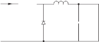
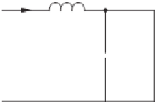
A buck converter is a step-down DC to DC converter. Figure 1.14 shows a typical buck
converter, which consists of two switches (a transistor and a diode), an inductor and a capacitor.
+
i
s
Q
i
o
L
+
v
s
C
Load
v
o
D
-
-
(a) Topology
+
i
L
i
o
i
L
i
o
L
L
+
+
v
s
C
Load
v
o
D
C
Load
v
o
-
-
-
(b) Mode 1 (Q: ON)
(c) Mode 2 (Q: OFF)
0
kT
T
(k+1)T
0
kT
T
(k+1)T
Time
Time
(d) Inductor current
(e) Capacitor voltage
Figure 1.14
Typical buck converter


Search WWH ::

Custom Search