Environmental Engineering Reference
In-Depth Information
28
2
24
P
1
P
2
Q
1
Q
2
0
20
−2
16
−4
12
−6
8
−8
4
−10
0
−4
−12
0
1
2
3
4
5
6
7
8
9
10
11
12
0
1
2
3
4
5
6
7
8
9
10
11
12
Time [s]
Time [s]
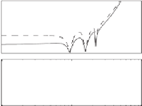
(a) Active power
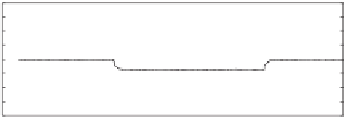
(b) Reactive power
28
10
9
E
1
E
2
24
20
16
5
12
8
2
4
0
0
1
2
3
4
5
6
7
8
9
10
11
12
0
1
2
3
4
5
6
7
8
9
10
11
12
Time [s]
Time [s]
(c) Voltage set-point
(d) THD of the output voltage
Figure 20.8
Experimental results at 1 : 1 power sharing when the non-linear load was changed
12
10
Z
o1
Z
o2
8
6
4
2
0
135
90
45
0
−45
10
2
10
3
10
4
Frequency (rad/sec)
Figure 20.9
Bode plots of the output impedances of the inverters for 2 : 1 power sharing
0.4
0.3
i
1
Circulating current
0.2
0.1
0
−0.1
−0.2
−0.3
−0.4
7
7.01
7.02
7.03
7.04
7.05
7.06
Time [s]
Figure 20.10
Circulating current at 2 : 1 power sharing


Search WWH ::

Custom Search