Environmental Engineering Reference
In-Depth Information
Table 19.1
Steady-state performance when supplying a non-linear load
Type of
Z
o
THD of
v
o
V
o
f
1
f
2
P
1
P
2
Q
1
Q
2
C
(479
μ
F)
17.86%
11.62
50.16
50.16
7.36
14.72
−
3.46
−
6.92
L
29.38%
12.15
49.81
49.81
8.40
16.81
−
1.40
−
2.80
R
18.54%
11.27
49.96
49.96
6.60
13.20
−
1.80
−
3.60
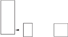
R-inverters. Moreover, when another inverter was added into parallel operation, the THD
of the output voltage dropped much more when the output impedances of the inverters are
capacitive than when the output impedance is resistive.
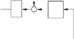
19.8 Robust Droop Control of L-inverters
19.8.1 Control Strategy
The same inherent limitations exist for the conventional droop control scheme corresponding
to L-inverters. Similarly as the cases of R-inverters and C-inverters, an additional loop to
regulate the output voltage can be bolted onto the conventional droop control to strengthen the
strategy and to improve the capability of voltage regulation. The resulting control scheme is
shown in Figure 19.18. It is able to share both real power and reactive power accurately even if
the per-unit output impedance is not the same and/or there are numerical errors, disturbances
and noises because, at the steady state, there is
K
e
(
E
∗
−
−
n
i
Q
i
+
V
o
)
=
0
.
(19.18)
This means
K
e
(
E
∗
−
n
i
Q
i
=
=
,
V
o
)
constant
E
*
-
K
RMS
e
-
E
i
1
P
i
n
i
s
v
o
v
ri
-
1
i
m
i
s
Q
i
ω
i
t+
δ
i
*
ω
Figure 19.18
Robust droop controller for L-inverters


Search WWH ::

Custom Search