Environmental Engineering Reference
In-Depth Information
S
=
P
+
jQ
S
=
P
+
jQ
1
1
1
2
2
2
°
V
∠
0
v
v
C
C
o
r
2
1
r
o
2
~
~
E
∠
Z
E
∠
δ
1
1
2
2
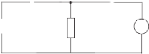
Figure 19.12
Two C-inverters operated in parallel
droop controller. It can be seen that the two inverters with the robust droop controllers were
still able to share the load very accurately in the ratio of 2 : 1, although
E
1
=
E
2
. The dynamic
performance did not change much either. The circulating current is very small and does not
contain noticeable fundamental component. It should be emphasised that the active power
sharing is still very accurate although the output impedances of the inverters are not resistive
over a wide enough frequency range and there is significant amount of harmonic current
components.
The only drawback is that the THD of the output voltage
v
o
is not satisfactory (22% for one
inverter and 16% for two inverters in parallel). However, this is expected because
R
oi
4
was used, which dominated the harmonic voltage drop on the output impedance and increased
the THD. It can be improved by using smaller
K
i
while maintaining the output impedance
resistive. A strategy to improve the output-voltage THD while maintaining accurate power
sharing will be discussed in Chapter 20.
=
K
i
=
19.7 Robust Droop Control of C-inverters
19.7.1 Control Strategy
Figure 19.12 depicts the parallel operation of two C-inverters. As reported in (Zhong 2012c)
and discussed above, the conventional droop control strategy is not able to accurately share
both real power and reactive power at the same time because there is no mechanism to make
sure that the voltage set-points are the same when numerical errors, noises and disturbances
exist. Also it is impossible to make sure that the per-unit output impedance is the same because
of component mismatches and parameter shifts. Hence, the voltage regulator bolted onto the
conventional droop controllers for R-inverters should also be bolted onto the droop controller
for C-inverters. This results in the robust droop controller shown in Figure 19.13. It is able to
share both real power and reactive power accurately even if the per-unit output impedance is
not the same and/or there are numerical errors, disturbances and noises because, at the steady
state, there is
K
e
(
E
∗
−
n
i
Q
i
+
V
o
)
=
0
.
(19.17)
This means
n
i
Q
i
=
constant
,


Search WWH ::

Custom Search