Environmental Engineering Reference
In-Depth Information
S
=
P
+
jQ
S
=
P
+
jQ
1
1
1
2
2
2
i
i
V
∠
0
°
2
R
R
2
v
~
v
~
E
∠
r
2
Z
E
∠
δ
r
1
1
1
2
2
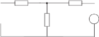
Figure 19.5
Two R-inverters operated in parallel
Note that, from (19.4), the reactive power
Q
i
is proportional to
−
δ
i
for a small power angle
δ
i
. In order to make the
Q
loop a negative feedback loop so that it is able to regulate
the frequency, the sign before
m
i
Q
i
in (19.6) is positive, which makes it a boost term. The
droop coefficients
n
i
and
m
i
are normally determined by the desired voltage drop ratio
n
i
P
i
−
ω
E
∗
and frequency boost ratio
m
i
Q
i
ω
∗
, respectively, at the rated real power
P
∗
and reactive power
Q
∗
. The frequency
v
ri
.
In order for the inverters to share the load in proportion to their power ratings, the droop
coefficients of the inverters should be in inverse proportion to their power ratings (Guerrero
et al.
2008; Tuladhar
et al.
1997), i.e.
n
i
and
m
i
should be chosen to satisfy
ω
i
is integrated to form the phase of the voltage reference
n
1
S
1
n
2
S
2
,
=
(19.7)
m
1
S
1
m
2
S
2
.
=
(19.8)
It is easy to see that
n
i
and
m
i
also satisfy
n
1
m
1
=
n
2
m
2
.
E
*
-
v
o
E
i
P
i
n
i
v
r
Q
i
1
i
m
i
s
ω
i
t+
δ
i
*
ω
Figure 19.6
Conventional droop control scheme for R-inverters


Search WWH ::

Custom Search