Environmental Engineering Reference
In-Depth Information
E
i
ω
i
E
*
*
ω
*
E
=
E
−
n
P
i
i
i
ω
=
ω
*
+
m
Q
i
i
i
Capacitive
Inductive
0
0
P
i
*
P
i
Q
i
*
Q
i
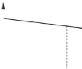
(a) for R-inverters
ω
i
E
i
E
*
*
ω
*
ω
=
ω
−
m
P
E
=
E
*
−
n
Q
i
i
i
i
i
i
Capacitive
Inductive
0
0
P
i
*
P
i
Q
i
*
Q
i
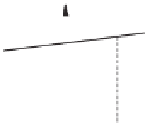
(b) for L-inverters
E
i
ω
i
E
*
*
ω
ω
=
ω
*
+
m
P
*
E
=
E
+
n
Q
i
i
i
i
i
i
Capacitive
Inductive
0
0
P
i
*
P
i
Q
i
*
Q
i
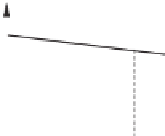
(c) for C-inverters
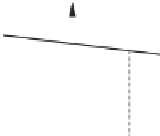
Figure 19.3
Droop control strategies
where
∼
means in proportion to. Hence, the conventional droop control strategy takes the
form
E
∗
−
E
i
=
n
i
P
i
,
ω
i
=
ω
∗
+
m
i
Q
i
,
This strategy, consisting of the
Q
−
ω
and
P
−
E
droop, is illustrated in Figure 19.3(a). In
this case,
P
Q
and
Q
=−
=
P
.
19.4.2 For L-inverters
When the output impedance is inductive,
90
◦
. Then
θ
=
EV
o
Z
o
EV
o
Z
o
V
o
P
=
sin
δ
and
Q
=
cos
δ
−
Z
o
.








Search WWH ::

Custom Search