Environmental Engineering Reference
In-Depth Information
S
=
P
+
jQ
i
Z
∠
θ
o
V
∠
0
°
~
~
E
∠
δ
(
v
)
(
v
)
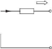
Figure 19.2
Power delivered to a voltage source through an impedance
Note that the voltage
V
o
drops when the load increases. This is called the load effect. In order
for the inverters to share the real power and reactive power in proportion to their power ratings,
appropriate control strategies should be deployed.
19.3 Power Delivered to a Voltage Source
Figure 19.2 illustrates a voltage source
0
◦
v
r
delivering power to another voltage source
V
o
∠
through an impedance
Z
o
∠
θ
. Since the current flowing through the terminal is
0
◦
E
∠
δ
−
V
o
∠
I
=
Z
o
∠
θ
E
cos
δ
−
V
o
+
jE
sin
δ
=
,
Z
o
∠
θ
the real power and reactive power delivered by the source to the terminal via the impedance
can then be obtained as
EV
o
Z
o
cos
V
o
Z
o
EV
o
Z
o
=
δ
−
θ
+
δ
θ,
P
cos
sin
sin
EV
o
Z
o
sin
V
o
Z
o
EV
o
Z
o
Q
=
cos
δ
−
θ
−
sin
δ
cos
θ,
where
is the phase difference between the supply and the terminal, often called the power
angle. This actually reflects the situation when a voltage-controlled inverter is connected to
an infinite bus where the terminal voltage is
δ
v
o
. The real power and reactive power can be
re-written as
⎡
⎣
⎤
⎦
.
EV
o
Z
o
δ
P
Q
sin
sin
θ
cos
θ
=
−
cos
θ
sin
θ
EV
o
Z
o
V
o
Z
o
cos
δ
−


Search WWH ::

Custom Search